Views: 1
InVidTech Product Guides 2024, Innovative Video Technology, InVid Tech, is a security equipment provider. Located in New York, on Long Island, InVid Tech’s headquarters are in a 10,000 square foot building that is home to both their offices and warehouse.
InVid Tech offers a wealth of knowledge and experience in the security industry, providing the latest technology to help our clients stand out from the competition.
InVid Tech is here to help you succeed, and as a company, we pride ourselves on the level of personal service we offer. We have an experienced team based in the United States, including Sales, Customers Service, Marketing & Tech Support. Additionally, there is support for Latin American Countries.
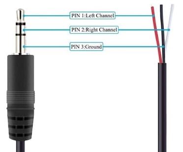
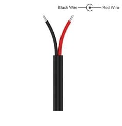
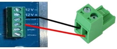
INVID-2WAYAUDIO Connection Types
Some information may vary depending on materials used.
InVidTech Product Guides 2024
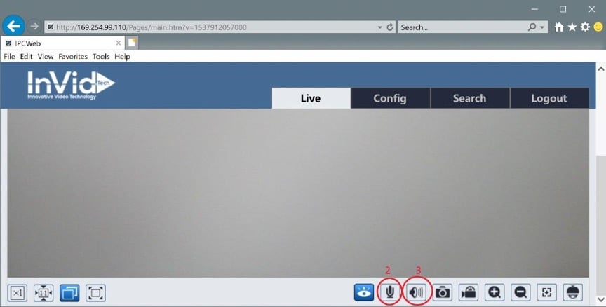
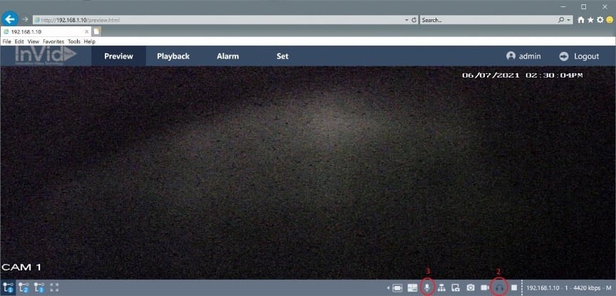
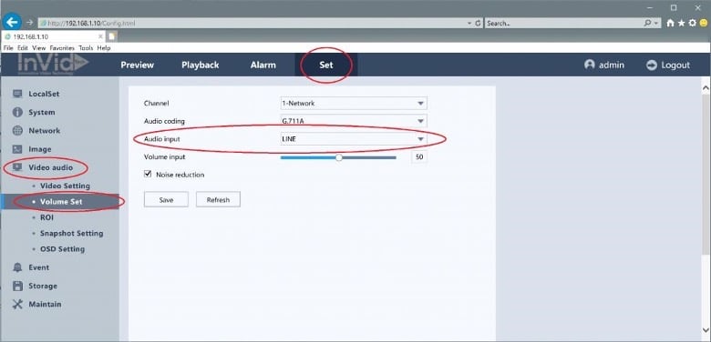
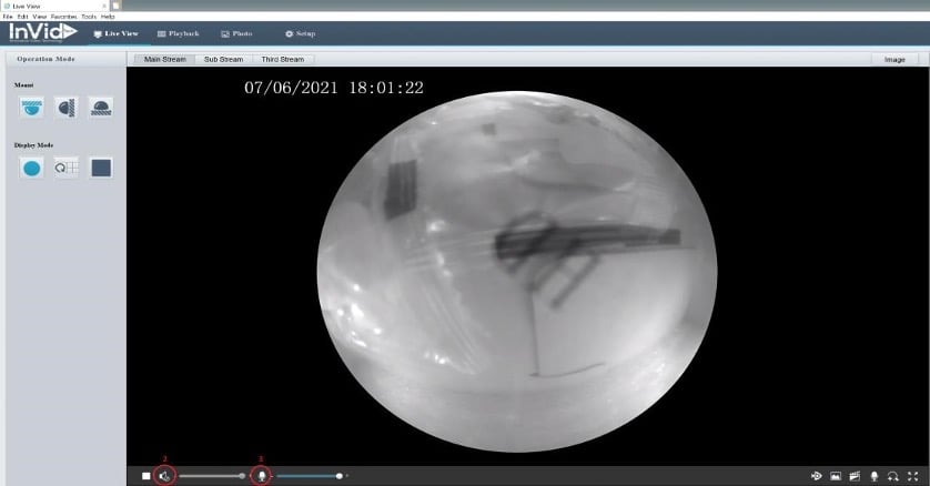
INVID-2WAYAUDIO Product Specific Connections
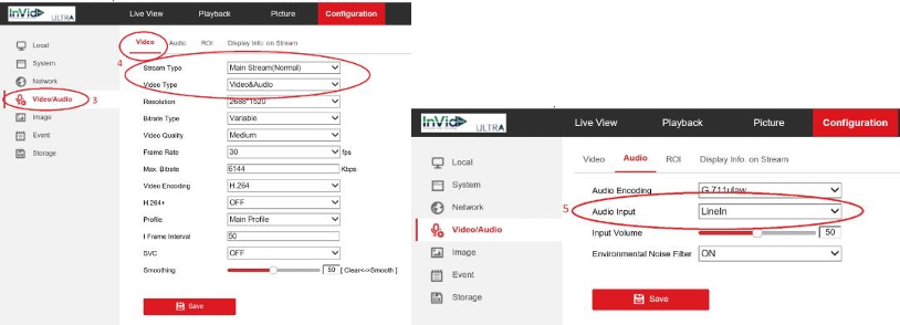
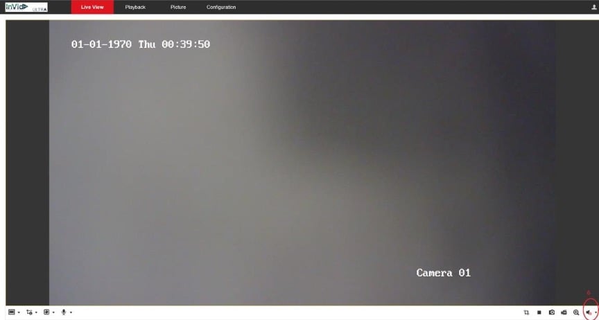
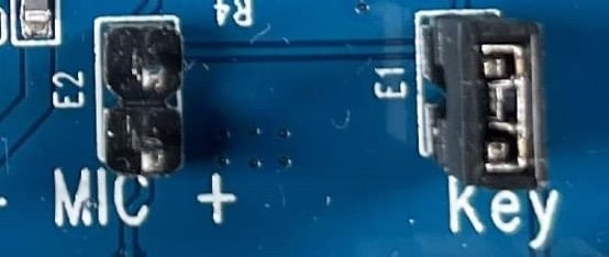
Audio Setup for INVID-2WAYAUDIO
If your camera does not have a built-in mic or speaker, no further action is required, you may skip step 4.
If your camera does not have a built-in mic or speaker, no further action is required, you may skip step 4.
If your camera does not have a built-in mic or speaker, no further action is required, you may skip step 4.
If your camera does not have a built-in mic or speaker, no further action is required, you may skip step 5.
Email Notification Setup
Step 1: Setting up a GMAIL account.
Johnschuman90@gmail.com
This does not have to be a Gmail address it can be anything you would like
2. Enabling Motion Detection Emails
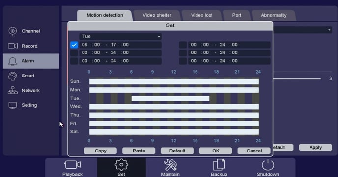
• “Schedule”, this arming schedule is setup for when you want this individual camera to send specific Actions selected. For instance, emails are sent 24/7 but Camera 1 only sends emails on Tuesday between 06:00-17:00
• “Copy/Paste” allows you to copy current channel and paste to another channel(s)
• “Action” make sure to check off “Send Email”
•Below, click on “Snapshot” and check off the channel number if you would like a picture along with your email notification
•Click on “Save” to apply
Elevate P2P QR Quick Setup
Elevate P2P QR Quick Setup
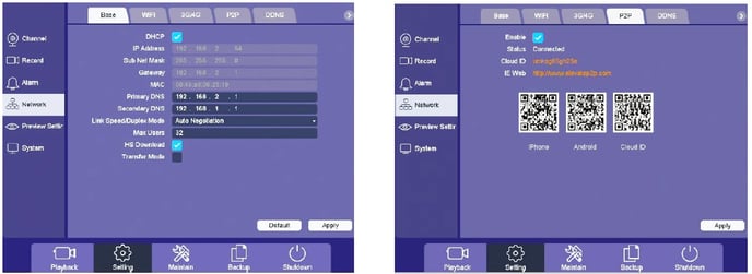
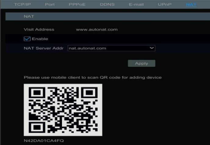
With P2P QR connection there is no need to set any ports, worry whether your uPnP is enabled within your router, do any port forwarding within your router or setup a DDNS name.
Setting up email notifications directly on the PAR-P2TEMPTABLET guide
It is advised to use Gmail as the sending email with the PAR-P2TEMPTABLET
while we have had success with other servers I.E. (Outlook, Yahoo, 365)
We cannot guarantee those platforms will work we can guarantee the use of Gmail as the sending platform.
This is in regards to the sending email only the recipients can be any email platform.
*Click on the images below to view in full screen.*
2. Follow the screenshots below to add the information into your email section of your tablet
Keep in mind please after each menu click save after any changes are made
This information has been entered via web ui in the example you may also accomplish this on the tablet itself from the login menu.
Paramont Upgrade Process
Paramont Upgrade Process, v1.0.3 to v1.0.4
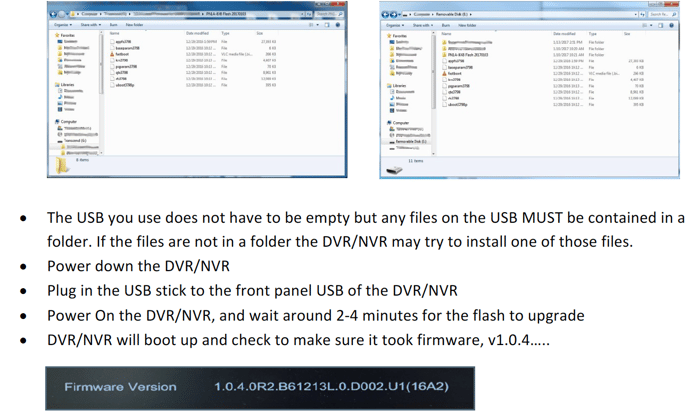
The Paramont upgrade process must be performed at the DVR/NVR itself, it cannot be done from the web. Please follow the steps below to successfully upgrade your DVR/NVR.
Paramount NVR Password Reset
Paramount NVR Password Reset
• Reboot the NVR/DVR so the start time is current date.
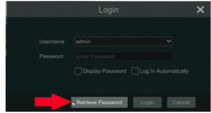
• Click the Retrieve Password button in the lower left corner.
*Click on the images below to view in full screen.*
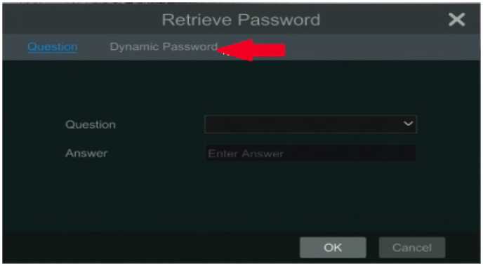
• Click Dynamic Password across the top
• Write down or take a picture of the Device Model, MAC Address and Current Time
• Next contact Customer Support with this information.
IMPORTANT NOTE: DO NOT shut the Retrieve Password window above until you have entered your new Dynamic Password. Doing so will change the time, which will change the Dynamic Password, the entire process will have to start over if closed prior to receiving the password.
PN3A-64 RAID Setup Guide
① Enable RAID
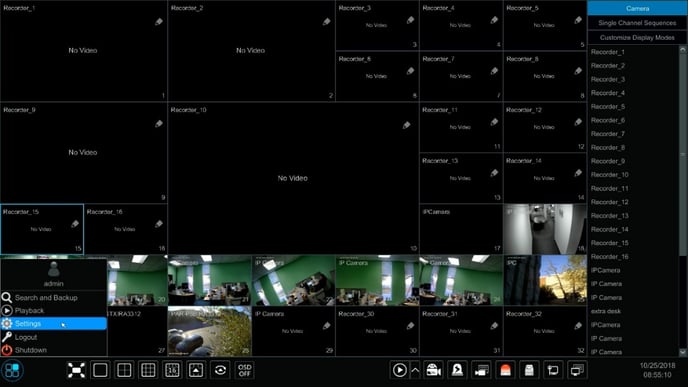
(Go to Start/Settings/Disk/Disk Mode)
*Click on the images below to view in full screen.*
② Create an array. (Go to Start/Settings/Disk/Physical Disk)
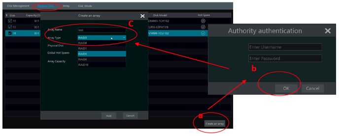
a. Click “Physical Disk” tab and then click “Create an array”.
b. Enter the user name and password which has the authority of Disk Management. If you don’t have one, you can use the user name and password that you login system (the default username: admin; the default password:123456).
c. Enter array name and select array type (like RAID5).
d. Select physical Disk.
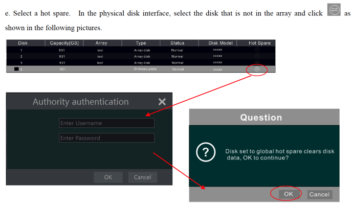
If you have 16 disks, please check 15 disks. The remaining one should be set to a hot spare.
If higher data security is needed, you can decrease physic disks and increase hot spare disks. Please set them as needed.
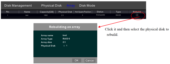
If one of your disks is broken, the disk indicator on the front panel will turn red. Of course, a warning tip will pop up if the relevant HDD exception alarm is set. You need to rebuild the RAID after you replace the broken disk with a new one.
Adding Paramont DVR/NVR to another Paramont NVR
Adding Paramont DVR/NVR to another Paramont NVR
*Click on the images below to view in full screen.*
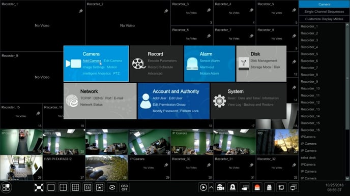
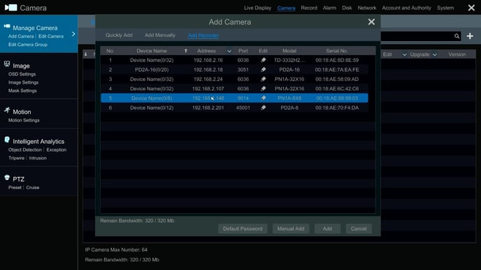
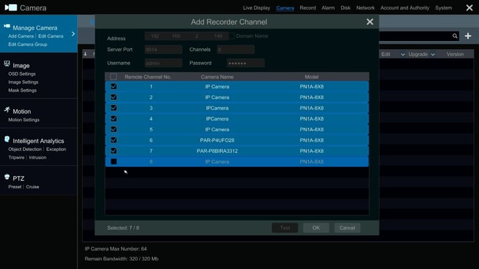
• Now under “Camera” select “Add Camera”
Instructions for Installing the MAC Plugin Paramont Series
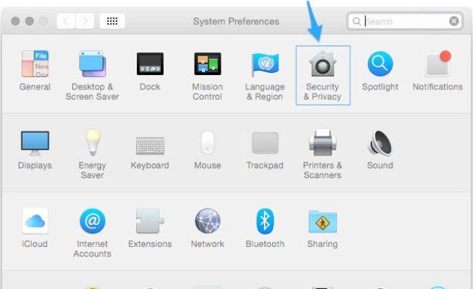
Instructions for Installing the MAC Plugin
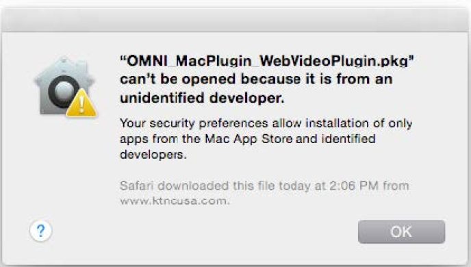
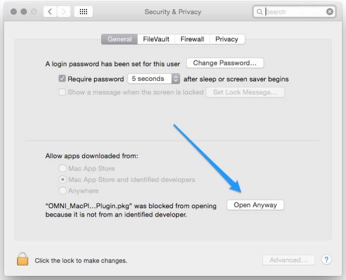
3. Select “Open Anyway” under Allow apps downloaded from:
*Depending on your settings you may need to put in your password and/or select the lock in the bottom left corner.
4. Once you have completed these steps your installation should start immediately. If not simply try opening the file again from “downloads” or wherever you have saved the file.
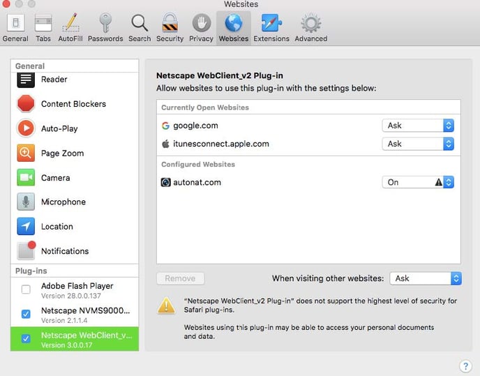
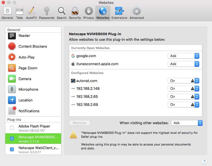
If you are having trouble viewing the cameras after you have updated to Mac OS High Sierra then go to Safari/Preferences/Websites/Plug-Ins on your left. Look for “Netscape NVMS9000 Plug-in” and “Netscape WebClient_v2 Plug-in”. Toggle the option under configure websites to “On”. Now force quit Safari then reopen and revisit the website. And it should now work. If you are still having issues please call Tech Support at 631-388-5700 option 3.
Paramont P2P QR Quick Setup
Paramont P2P QR Quick Setup
With P2P QR connection there is no need to set any ports, worry whether or not your uPnP is enabled within your router, do any port forwarding within your router or setup a DDNS name.
*Click on the images below to view in full screen.*
Not connected? Here are some things to check
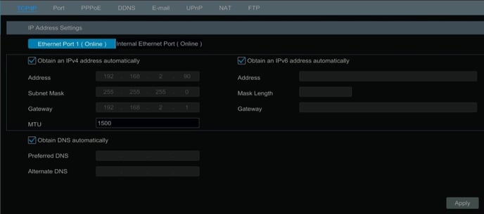
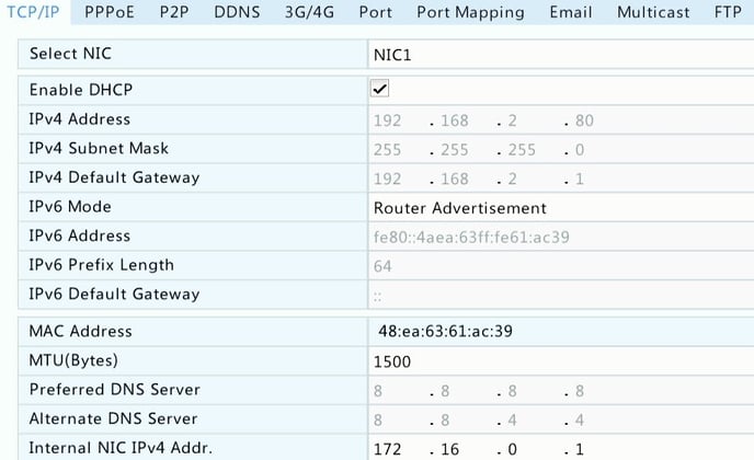
4. Sometimes though DHCP is “Succeed” the DNS is pulling the router IP, which will cause the device not to connect. You can disable the “Obtain DNS Automatically” and enter in Google’s addresses (8.8.8.8 & 8.8.4.4)
5. Can you connect to the device via the LAN IP, whether it’s the DHCP address or the address you manually gave it (because DHCP was disabled) via the Internet Explorer to ensure it has network connectivity
6. Was the NAT definitely “enable” and saved, check back (Start Button/Settings/Network/NAT)
7. If all else fails, you can always reach out to the InVid Tech technical Support Team
Viewing your Paramont Device Online or from Mobile App
Viewing from your Web Browser (Internet Explorer):
Viewing from your InVid Vision mobile app:
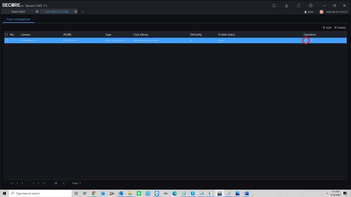
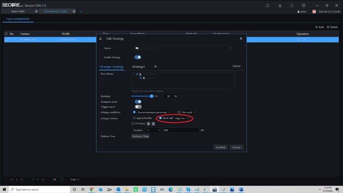
Setting up email notifications directly on the Secure CMS guide
It is advised to use Gmail as the sending email with the SEC-BODYTEMPCAM1.
while we have had success with other servers I.E. (Outlook, Yahoo, 365)
We cannot guarantee those platforms will work we can guarantee the use of Gmail as the sending platform.
This is in regards to the sending email only the receiving email can be any platform.
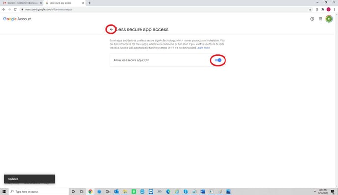
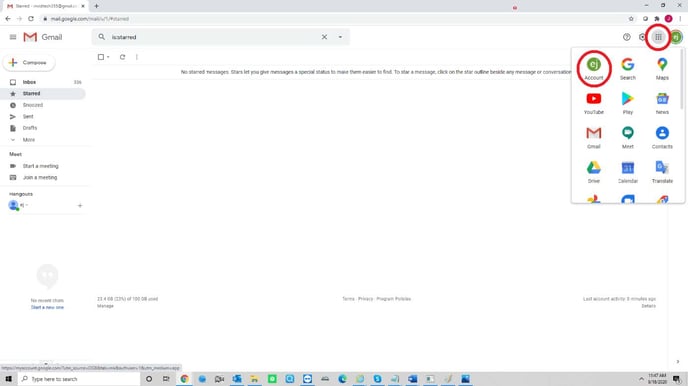
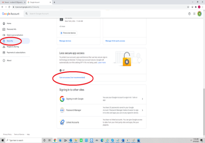
1. Allow “Less Secure Apps” on your Gmail account the screenshots below show you how to accomplish this. (Start by logging into your Gmail Account)
*Click on the images below to view in full screen.*
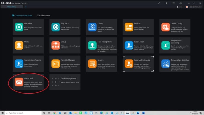
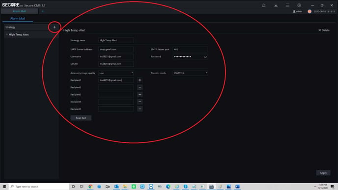
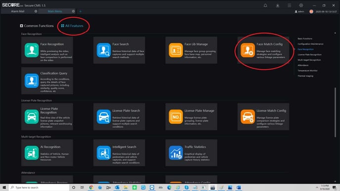
2.Open the Secure CMS (Below are the screenshots of the next steps once your CMS is opened)
Human Body Temperature Camera Configuration Guide (SEC-BODYTEMPCAM1)
Human Body Temperature Camera Configuration Guide
(SEC-BODYTEMPCAM1)
**Please Note: Cameras Default IP address is 192.168.1.121. IP Utility can be downloaded off our website at http://info.invidtech.com/securedownloadspc
1. Log into the cameras web interface on Internet Explorer (IE), default username is “admin” and default password
are “1234567u”. Make sure to download the new plugin.
Note: close ALL browser tabs while installing the plugin.
2. Parameter Configuration (Configuration/Human Thermometer/Parameter Configure)
2.1 Enable face detection
2.2 Draw the area according to the real scenario, there is a maximum of 8 areas supported. We usually use one
detection area to cover where people could potentially appear in, recommended distance is 9 to 16 feet (3-5 meters) for capturing.
*Click on the images below to view in full screen.*
2.3 Leave the Display Trace Info at “Mode 1”
2.4 Show Detection Area, can turn On or Off
2.5 For Confidence Coefficient, we suggest keeping the default value (Mid). It’s for the face matching level with the built-in algorithm.
2.6 Area ID is for the selected areas if you choose more then one main area, up to 8 totals. We suggest keeping this at one and focusing on the main point of entrance.
2.7 For Face Pixel Minimum and Maximum, we suggest keeping the default value (70/1000). Only faces in this range will be detected.
2.8 There are two different Snapshot Modes:
Timing: ‘upload interval’ is associated with ‘timing’, camera will upload one picture every 5 seconds (Suggested).
Optical: ‘snapshot count’ is associated with ‘optical’, camera will upload the best face picture in 5 seconds.
2.9 For Upload Image Interval we suggest leaving at 5 seconds (1-10 second range).
2.10 For Yaw Degree, Tilt Degree, Pitch Degree and OSD Overlay Snapshot, we suggest keeping as default.
2.11 FTP Upload Image Matting and FTP Upload Whole Image are if you are using the camera as a standalone
device, no CMS or NVR, and wish to save the facial snaps to an FTP.
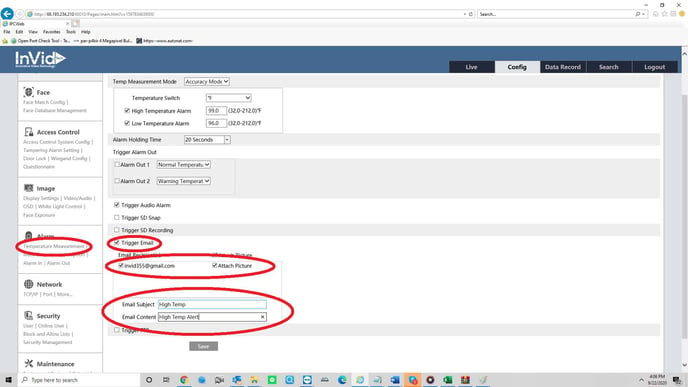
2.12 Temperature Parameters
Enable this field and leave all as DEFAULT except LENGTH UNIT and MOUNT DISTANCE
IF YOU SWITCH TO FAHRENHEIT THE FIELDS STILL STAY AS DEFAULT (Except Length/Mount Distance, mentioned above)
DEPENDING ON THE SELECTION OF “LENGTH UNIT” (METERS/FEET), ALL DISTANCE FIELDS WILL BE CONSIDERED IN THOSE UNITS!
[IMPORTANT] Set the mount distance according to the real installation, whose value should be the horizontal distance from the detection area to the camera.
Hit ‘apply’ to save the settings.
2.13 Face Alarm Linkage
IF SWITCHED TO FAHRENHEIT YOU MUST ADJUST “ALARM TEMPERATURE”, 99.5-100.5F (Default Celsius is 37.30)
3. [IMPORTANT] Thermal Mapping (Configuration/Human Thermometer/Thermal Mapping)
This step is mainly for matching the thermal image with the visible image, which can ensure the measurement accuracy. The Black Body device (Infrared Calibrator) MUST be in the Field of View of the thermal image. The thermal image is a FIXED LENS and is a smaller field of view then the standard image.
3.1 There are eight groups of ID, and each group ID contains three points. If using One area, then you do not have to set groups 2-8.
3.2 Pick out three points that you can clearly see in the thermal image, mark them with point1, point2 and point3.
3.3 Find the three locations of the three points in the visible image and mark them with the same point numbers associated with those in thermal image.
Note: Suggested to choose three points far away from one another, so the triangle of can cover 70% of the image.
3.4 Hit ‘apply’ to save the settings.
3.5 Test if the rectangle can correctly surround the face, and perfect it by adjusting the three points.
4. Thermal calibration (Configuration/Human Thermometer/Thermal Calibration)
*Distance between Camera and Calibrator MAX distance is 16 FEET*
4.1 Install the blackbody properly where the camera can see it (within the thermal image). The blackbody needs
to be powered on for at least 20 mins to reach to a stable temperature.
4.1.1 The Infrared Calibrator will ALWAYS display in CELSIUS; the stable temperature is ~40C
4.2 Enable.
4.3 If you turn on ‘Display Area Info’, the blackbody (Infrared Calibrator) will also be shown with temperature on thermal image.
4.3.1 Draw box around your calibrator
4.4 Target Temperature: If using Celsius leave as 40C, if using Fahrenheit change to 104F (Default)
4.5 For Distance, put the real installation distance between the camera and Black Body (Infrared Calibrator). No more then 9-16 feet (3-5 meters). Distance is in Meters or Feet, depending what you selected under the Parameter Config menu.
4.6 Keep the ‘Emission Rate’ as the default value.
4.7 Hit ‘apply’ to save the settings.
Setting up email notifications directly on the SEC-BODYTEMPCAM1 guide
Setting up email notifications directly on the SEC-BODYTEMPCAM1 guide
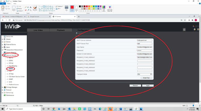
It is advised to use Gmail as the sending email with the SEC-BODYTEMPCAM1.
while we have had success with other servers I.E. (Outlook, Yahoo, 365)
We cannot guarantee those platforms will work we can guarantee the use of Gmail as the sending platform.
This is in regards to the sending email only the receiving email can be any platform.
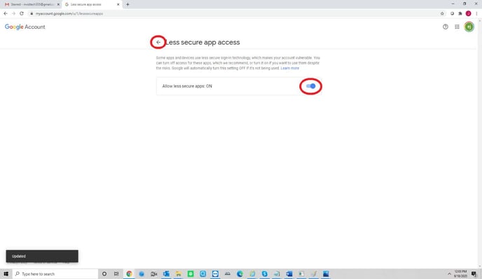
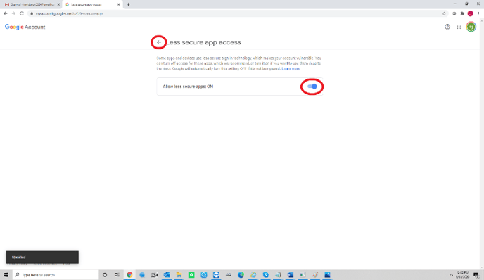
1.Allow “Less Secure Apps” on your Gmail account the screenshots below show you how to accomplish this. (Start by logging into your Gmail Account)
*Click on the images below to view in full screen.*
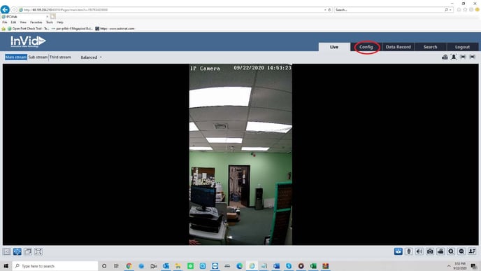
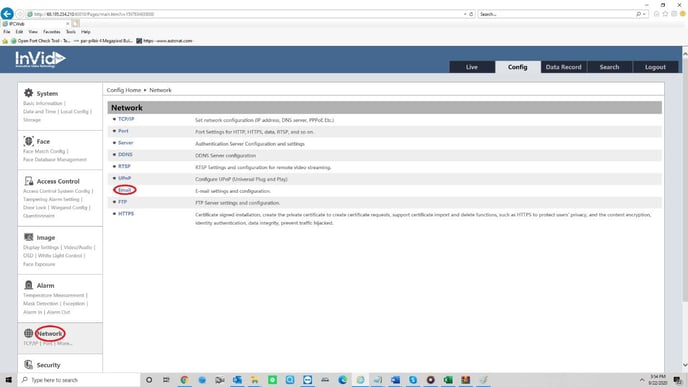
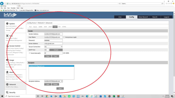
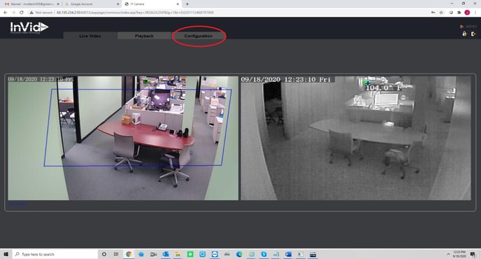
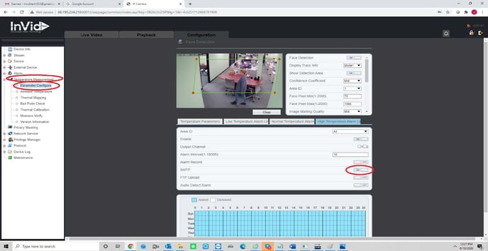
2. Log in to the SEC-BODYTEMPCAM1 (Below are screenshots of the next steps in setting up email notification the SMTP info for Gmail )
Ultra Email Notification Setup
Step 1: Setting up a GMAIL account.
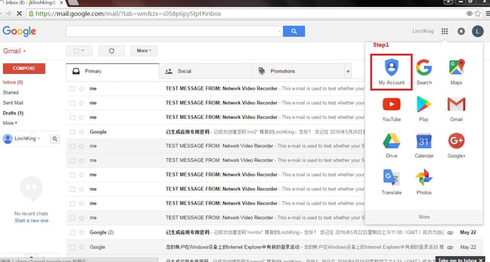
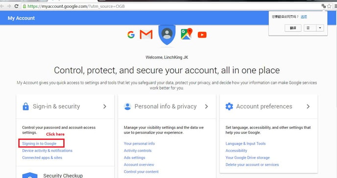
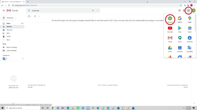
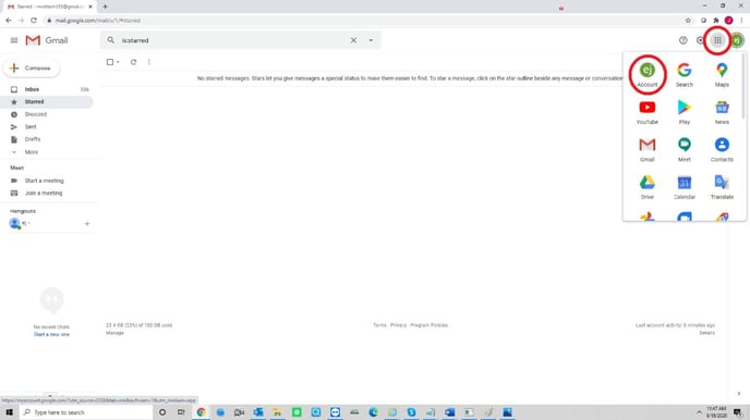
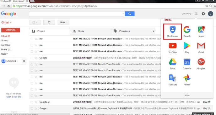
1. Go to My Account setting page,click on the square and click my account.
*Click on the images below to view in full screen.*
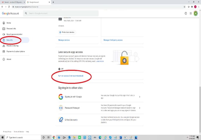
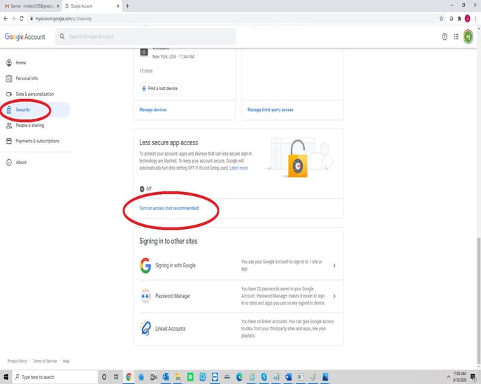
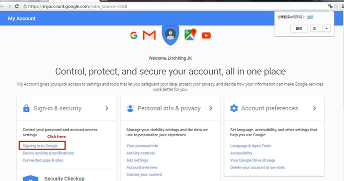
2. Click Signing in to Google.
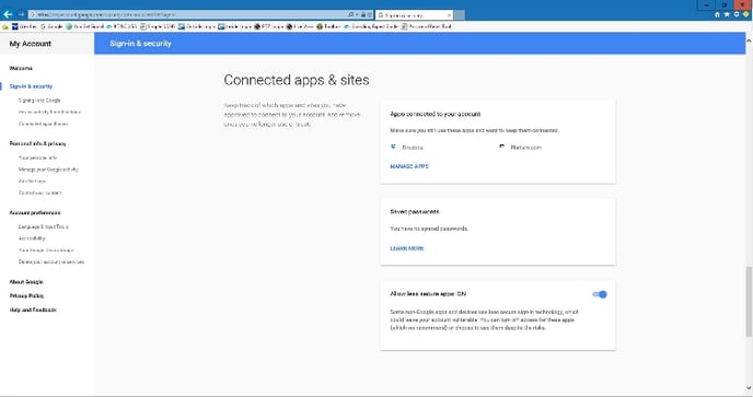
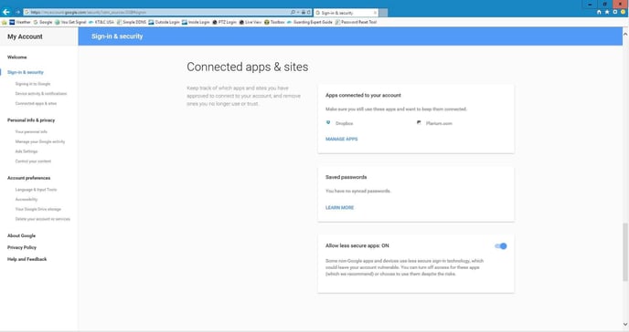
3. Click Allow less secure apps on.
If you are logging in through the web interface.
Step 2: Set Up Email Account in DVR/NVR.
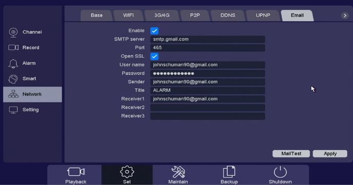
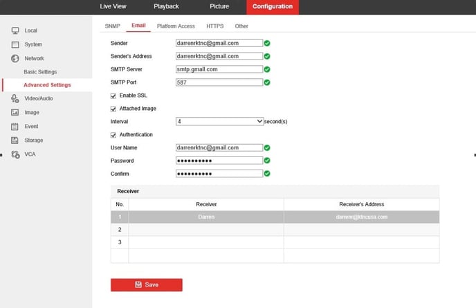
Go to Configuration/Network/Advanced Settings/Email
Follow the picture below, just change the User Name to yours and the Sender’s Address to yours and all other info in the fields as shown. User name and Senders address must be the same. The Receivers email addresses can be anything you want.
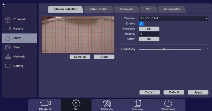
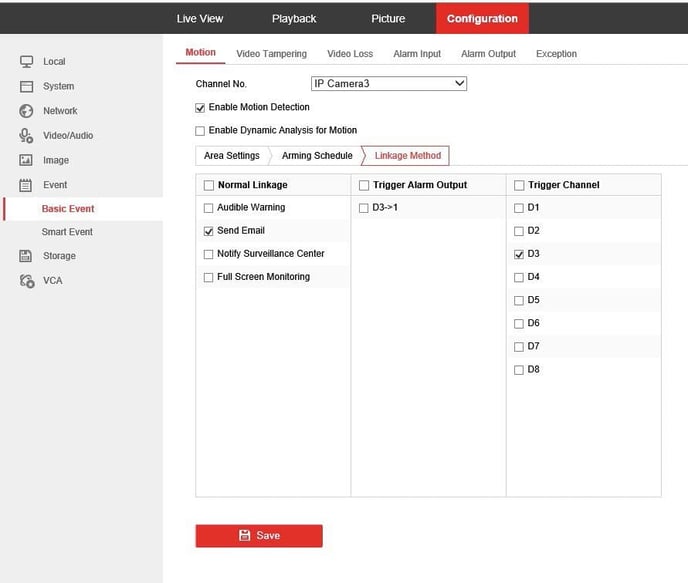
Step 3: Linking Email to Motion Go to Event/Basic Event/Motion.
Click enable motion for the camera that you want to use. Make sure that the grid is over the field of view were you want motion to be detected. Set the sensitivity at least to the middle setting. The setting all the way to the left is OFF. Next click the Settings button and choose Linkage Action and check off Email.
If you are logged into the DVR/NVR directly.
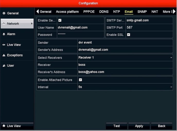
Step 2: Set Up Email Account in DVR/NVR. Go to Menu/Configuration/Network/Email
Make sure the DVR/NVR is fully networked then follow the picture below, just change the User Name to yours and the Senders Address to yours and all other info in the fields as shown. The Receivers email addresses can be anything.
Step 3: Enable Email Alerts.
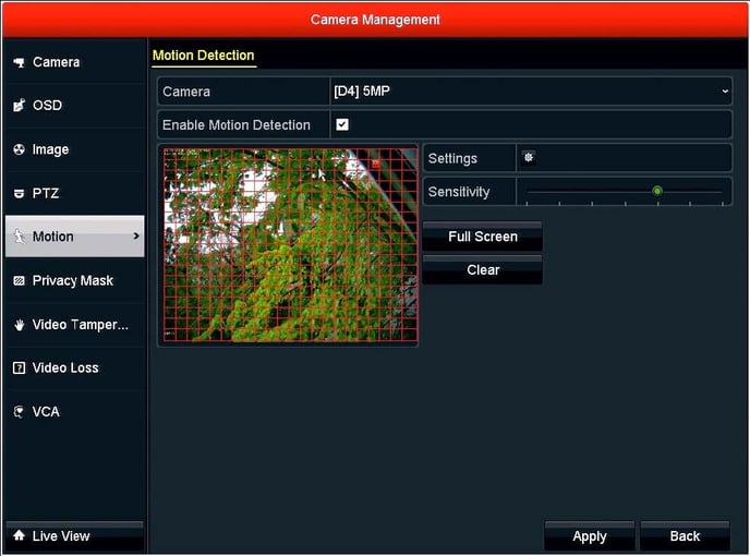
Go to Menu/Camera/Motion then enable motion for the camera that you want to use. Make sure that the grid is over the field of view were you want motion to be detected. Set the sensitivity at least to the middle setting. The setting all the way to the left is OFF.
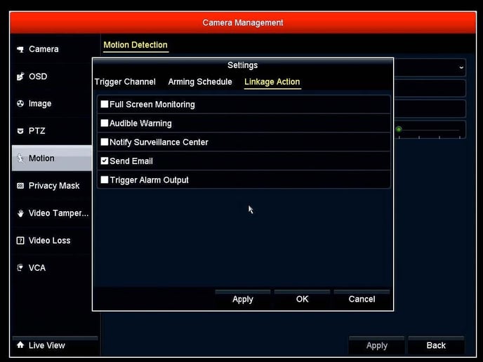
Next click the Settings button and choose Linkage Action and check off Send Email then press Apply and then Ok.
You are now ready to receive Email Notifications.
Ultra Device Password Reset
Ultra Device Password Reset
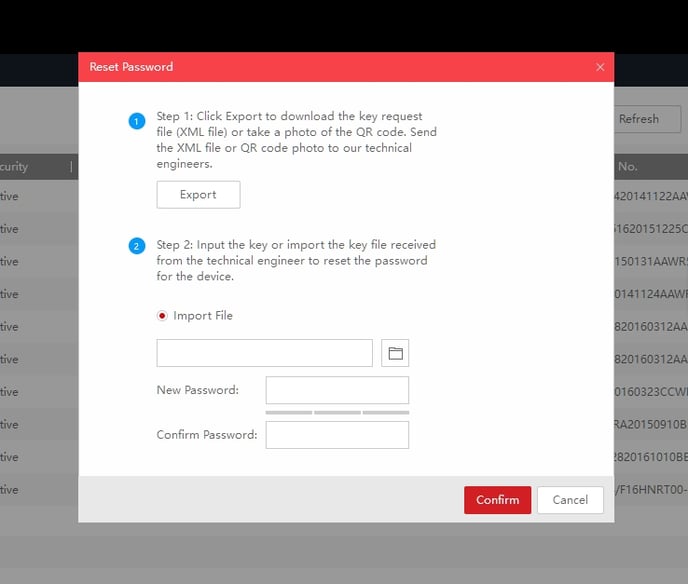
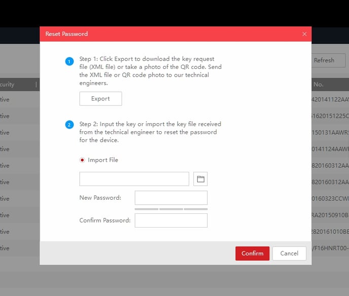
1. Connect a PC to the same network as the Device is on or the Device directly to the PC. Run the SADP tool, locate and select your Device and hit “Forgot Password”.
*Click on the images below to view in full screen.*
2. A window will open, click Export to save the file. This is the file to send to Technical Support.
3. When you receive the new file from Technical Support, click the Browse tab to import file and enter a new password then press confirm.
Please Note: The file generated from the camera is DATE sensitive so once generated the camera cannot be rebooted.
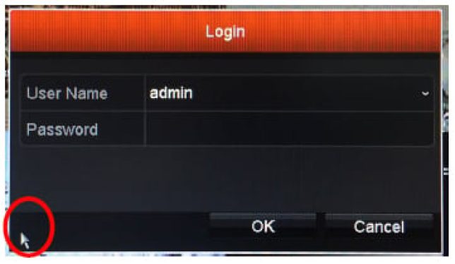
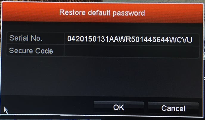
Ultra DVR/NVR Customer Passcode Reset
Password Reset Procedure
UN1A-16X8 and UN1A-32X16: Going beyond the Plug-and-Play port count
UN1A-16X8 and UN1A-32X16
Going beyond the Plug-and-Play port count
ULTRA-IP NVRs have a fixed number of Plug-and-Play ports on the rear panel. The maximum number of fully Plug-and-Play cameras supported by an ULTRA-IP NVR is the same as the number of Plug-and-Play ports on the rear panel. In addition, the maximum number of IP cameras that can be connected through the PoE switch on the rear panel is the same as the number of Plug-and-Play ports on the rear panel*.
For the UN1A-4X4 and UN1A-16X16XL, that is rather straightforward. Cameras can be connected as Plug-and- Play to the PnP ports. Cameras can be connected as “manual” configured cameras through either the PnP ports or the LAN/WAN network port. Either way, on these two models, the maximum number of connected cameras is exactly equal to the number of PnP ports on the rear panel. If any camera is connected via the LAN/WAN network port, that is one less camera that can be connected to one of the PnP ports.
The UN1A-16X8 and UN1A-32X16 are a different story. Each is capable of connecting up to twice the number of cameras as there are PnP ports on the rear panel. Given that a maximum of 8 cameras can be connected thought the PnP switch on the rear of the UN1A-16X8 and a maximum of 16 cameras* can be connected through the PnP switch on the rear of the UN1A-32X16, how are the additional 8/16 cameras connected? They must be connected through the Gb/s LAN/WAN network port on the rear panel of the NVR.
*Click on the images below to view in full screen.*
*While additional cameras may be connected to the internal switch, as the switch capacity is 100Mb/s spreading that bandwidth across more than 16 cameras may reduce system performance and reliability.
Does this mean that for the additional 8/16 cameras, or any cameras connected though the LAN/WAN port there is no Plug-and-Play convenience? Not exactly. Depending on the network setup, if they are KT&C Plug- and-Play capable cameras, it is possible to quickly and conveniently set up and access those cameras.
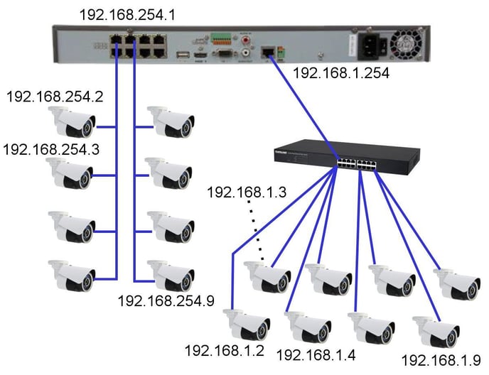
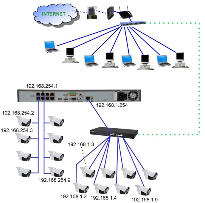
Consider this network connection setup. The Plug-and-Play PoE switch IP address is 192.168.254.1; the PnP IP cameras 1~8 are assigned addresses 192.168.254.2~192.168.254.9 respectively. Any cameras beyond those 8 must be powered separately (by PoE or 12VDC) and connected through a separate LAN switch (gigabit strongly recommended). Fortunately for ULTRA-IP PnP cameras, once the LAN/WAN port is assigned a static IP address it can discover attached ULTRA-IP PnP cameras and will assign them IP addresses.
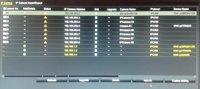
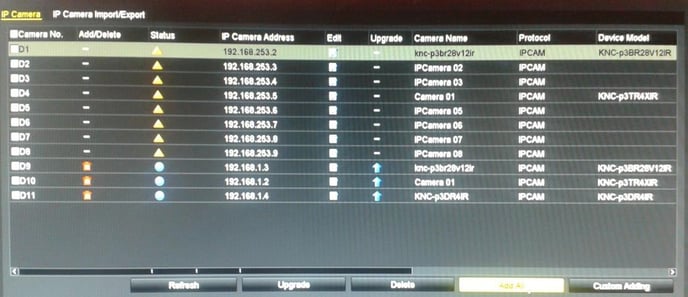
In this example, the LAN/WAN port is assigned an IP address of 192.168.1.254. The NVR automatically discovers and assigns the IP addresses 192.168.1.2~192.168.1.9 to the eight cameras on that port. Once this process has completed, those 8 cameras are available for ‘one click adding’ [Add All] to become cameras 9~16. At this point one has a working, stand- alone 16 camera NVR system. As an example:
Discovered cameras ready to “Add All”
Cameras 9~11 Added and Connected
If this were a ‘stand alone’ system it would be complete. The NVR has local display for live and playback; additional monitoring PCs can be connected to the 192.168.1.0 network. However, in our modern ‘connected’ world local access alone is not sufficient. We need to be able to access this system remotely using ULTRA CMS or ULTRA Remote smart phone apps. To accomplish this, we must link the LAN/WAN port on the NVR with a network which has access to the Internet. Can we do this simply by connecting the auxiliary switch directly to an existing LAN/WAN as shown below?
While this may be possible, it is unlikely to work and may be unreliable. IF the existing network happens to also use the same addressing scheme as the LAN/WAN port on the NVR (e.g. 192.168.1.X), the two networks can be joined. However, there is nothing to prevent two devices from trying to use the same IP address (an address conflict).
Camera network address are assigned by the NVR without regard to any other constraints. The DHCP host on the existing LAN also hands out DHCP addresses that might duplicate/conflict with camera addresses. There may also be manually assigned static IP addresses on that other network which conflict with the NVR itself or with the IP cameras (initially, or at some time in the future).
If the addressing scheme on the two networks is different, no communication between them can take place.
Trying to directly co-join these two networks is likely to be more trouble than it is worth in the long term. Still, the NVR needs a path to the Internet, and perhaps needs to be accessible from some or all of the PCs on the home/office LAN/WAN.
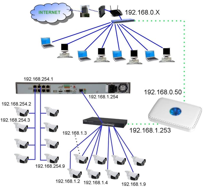
One simple way to connect two networks with different network numbering schemes is a router. A simple home/office router will likely suffice. The “LAN” side of the router connects to the auxiliary camera network switch. The router LAN port is assigned a compatible IP address (e.g. 192.168.1.253). The “WAN” side of the router is connected to the home/office LAN/WAN and is assigned a static IP address compatible with that network (e.g. 192.168.0.50).
Since routers function as DHCP hosts, to avoid conflicts the DHCP function in the additional router should either be disabled, or restricted to a very limited address range, e.g. 192.168.1.245~ 192.168.1.252. This DHCP capability aids in the connection of wired or wireless PCs and other devices to that NVR/camera network for monitoring and diagnostic purposes.
Since routers also function as firewalls, we need to make the NVR accessible from the home/office LAN/WAN side. One way to do this is to indicate the IP address of the NVR (192.168.1.254) as being in the “DMZ” for the router. This completely exposes the DMZ device address to the “WAN”. From the home/office LAN/WAN 192.168.0.50 effectively becomes the IP address of the NVR.
Another way to set up access to the NVR through this router is using the automated “NAT” feature in the NVR. This will open up the IP ports through the AUXILIARY router that joins the secondary camera network with the home/office LAN/WAN. It will be necessary to manually configure the existing home/office LAN/WAN router to forward the necessary ports to the auxiliary router, so it can pass that traffic on to the NVR.
DDNS on the NVR should have no problems. Contact from the recorder to the DDNS server (presuming that the DNS information has been properly entered in all router and NVR network configuration settings) is outbound and should be unrestricted. Inbound, the DDNS name directs the communication to the site’s WAN IP address, and port access should be forwarded by the site’s WAN router onward to the auxiliary router, which in turn forwards the requests to the recorder.
Guarding Expert Instructions
Guarding Expert Instructions
o Alias: Nickname or what you want to call the DVR/NVR, i.e. HOME
o Register Mode: HiDDNS
o Device Domain: is the DDNS name you made at DVR/NVR, i.e. 123amityst
o User Name: the user name needed to access DVR/NVR
o Password: the password needed to access the DVR/NVR
o Camera No.: By default this is at “1”, once all the above info is added correctly and saved this number will automatically change to the amount of cameras connected to the DVR/NVR.
o Alias: Nickname or what you want to call the DVR/NVR, i.e. HOME
o Register Mode: IP Domain
o Address: Static WAN IP address entered here, must be STATIC (will not change)
o Port: Server Address Port that was opened in DVR/NVR
o User Name: the user name needed to access DVR/NVR
o Password: the password needed to access the DVR/NVR
o Camera No.: By default this is at “1”, once all the above info is added correctly and saved this number will automatically change to the amount of cameras connected to the DVR/NVR.
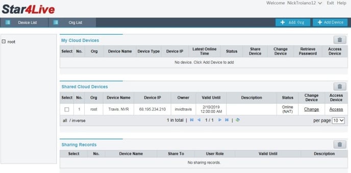
Vision P2P QR Setup & Viewing Instructions: Quick Setup Guide
Vision P2P QR Quick Setup
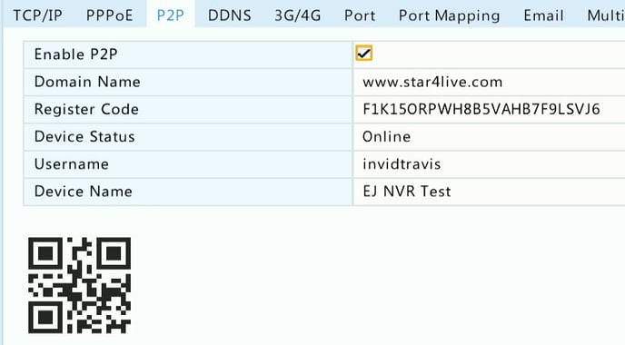
With P2P QR connection there is no need to set any ports, worry whether or not your uPnP is enabled within your router, do any port forwarding within your router or setup a DDNS name.
Go back to your NVR (Menu/System/Network/P2P) and you will now see your Device Status is “Online”
Not connected? Here are some things to check
Viewing your Vision Device Online or from Mobile App
Viewing from your Web Browser (Internet Explorer):
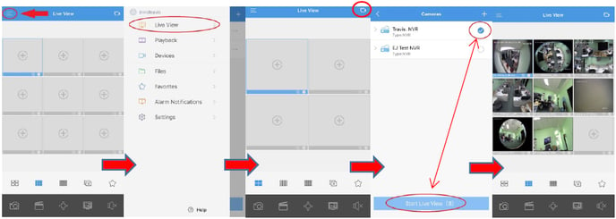
Viewing from your InVid Vision mobile app:
