Views: 25
How do I set up remote access to my Hikvision device and change the port numbers that it uses?
To remotely access your device simply means to connect to it while you are using a different internet network to that which your device is connected. If you connect to your Hikvision device which is at home while at work, on holiday, or even at the pub, you are remotely accessing it.
The simplest way to do this is to add it to and access it in the Hik-Connect mobile app, which is covered in the next part of this Megathread. However, Hik-Connect’s access to your device configuration is restricted. If you want to extract footage or just want to view your footage in an internet browser or iVMS-4200, then you will need to set up remote access. This can be done by “Port Forwarding”, which is the process of opening the ports on your router that your devices are using. These ports are closed by default for security purposes.
There are up to 6 different port types which you can configure on your device. Each of these will be on a different port number on your router, the main types that are used for remote access are explained below:
HTTP Port: The port needed for accessing the web browser interface (and configuration menu) for the camera or NVR.
RTSP Port: This is used to access the RTSP stream of a camera. The RTSP stream is used for viewing a camera’s live stream, normally on a third-party service, like when embedding the stream on your own webpage.
Server Port: This is the port used by software for access to the device, such as iVMS-4200.
HTTPS Port: Similar to the HTTP port, but offers a more secure connection as it encrypts the data being accessed through this port.
The steps below will take you through the relatively simple procedure of port forwarding, leaving you ready to remotely access your devices from anywhere with an internet connection.
PLEASE NOTE – We recommend changing these port numbers from the defaults. Leaving them at their default values can leave you vulnerable, especially if you don’t use strong passwords.
Step 1:
To find and change the ports on your router that your device is connected to, go to:
In the web browser GUI:
Configuration > Network > Basic Settings > Port No.
Or…
In the local GUI:
System > Network > TCP/IP > NAT
If you’re using the web browser GUI…
You will be taken to this page. All you need to do now is set the port numbers as you please, and click Save:
If you’re using the local GUI on an NVR…
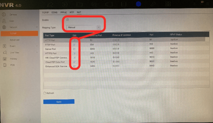
Now, make sure that the Enable box is ticked, and the Mapping Type is set to Manual.
You should now be able to see a table with a column showing each of the Port Types and port numbers that your NVR is connected to, and another with the option to Edit these ports, by clicking on the notepad icon for each port type:
Alter any of the port numbers you like, just make sure to click OK and then Apply once all ports are set to something that you’re happy with:
Step 2:
Now that you know the port numbers, you can turn your attention to getting these ports on your internet router opened to facilitate remote access. You need to make sure you have the following information about the network to do so:
NB – To find the LAN address of your router, please see the guide that applies to your operating system below:
How-to: How do I find my router and Mac’s IP address using a Mac?
How-to: How do I find my router and PC’s IP address using a Windows PC?
Step 3:
Now, using this Gateway address, log into your router in a web browser browsing for it in the address bar; This is where you will “open” or “forward” your ports. For remote access in iVMS-4200 or a web browser, you will need to forward the HTTP, RTSP and Server ports.
The process of port forwarding itself varies with each router model. If you’re not sure how to do this on your router, use Portforward.com to search for the model and corresponding guide for forwarding the ports in use by your Hikvision device.
Step 4:
Once you have opened these ports on your router you should be ready to access these remotely. To do this, just search for your public IP address, followed by a colon and then the port number in a web browser.
E.g. this URL will allow you to remotely connect to the default HTTP port, 80:
123.45.678.90:80
If you’re not sure what your public IP address is, then you can check this easily on WhatIsMyIPAddress.com. (Just make sure that you are not using any VPN software at the time.)
NB – Another quick way to check your ports are open is to use the website CanYouSeeMe.org. Once there, enter your public IP address and port number and then click Check Port. If you are met with a “Success:” message, then your ports have been forwarded properly. If you receive an “Error:” message, then you will need to revisit the above steps.
How do I set up events and email or push notifications on my Hikvision camera?
Video Analytics, or “VCA events”, are some of the most useful features available on a Hikvision camera. Using these will mean that your footage is analysed in real-time for any activity or abnormalities with your system that you would like to receive an alert for. The different events that are available currently (which ones are available varies which each model of camera) include:
This guide will cover the setup of three of the most popular event options:
Motion Detection – This is one of the first AI options that was introduced and will analyse your footage for any moving object in a specified part of your scene and can alert you as soon as it is detected. As it detects motion in its most basic sense, it uses less of a camera or NVR’s processing power than the other event options, meaning it is always available regardless of your video compression settings.
If you are not using a device with AcuSense then this option will give you the most false-positive alerts, as it offers the fewest ways for filtering out moving objects that you are not interested in, such as object size and the direction or duration of the motion.
Intrusion Detection – This is similar to motion detection in that it will alert you when a moving object is detected within a predefined “intrusion zone”. However, this is better if you want more control over when you are alerted as it will only notify you when a moving object enters the zone, rather than whenever movement occurs within it. This event type also allows you to specify the size of trigger objects, as well as how much of an object enters the zone and for how long before you are alerted.
Line Crossing Detection – This option is particularly useful for various entrances, boundaries, and roads, etc., as it allows you to draw a line in your scene so that you are notified when an object moves across that line. Importantly, you can specify the direction(s) of movement across the line on which you are notified. Like intrusion detection, you also have more control over the size of the trigger object and how much of it must cross the line.
Note – Before starting, you will need to check that your Default Gateway and DNS Server are correctly set up in your device’s network parameters, as these need to be right in order for you to be sent email notifications. To check these, please see part 2.
Section 1: Setting up motion detection
Step 1:
Connect to your device’s web browser interface by browsing for its IP address and log into it. If it is recording to an NVR, then connect to this, as this is where you should set your events from.
Step 2:
Once you’re in, navigate to:
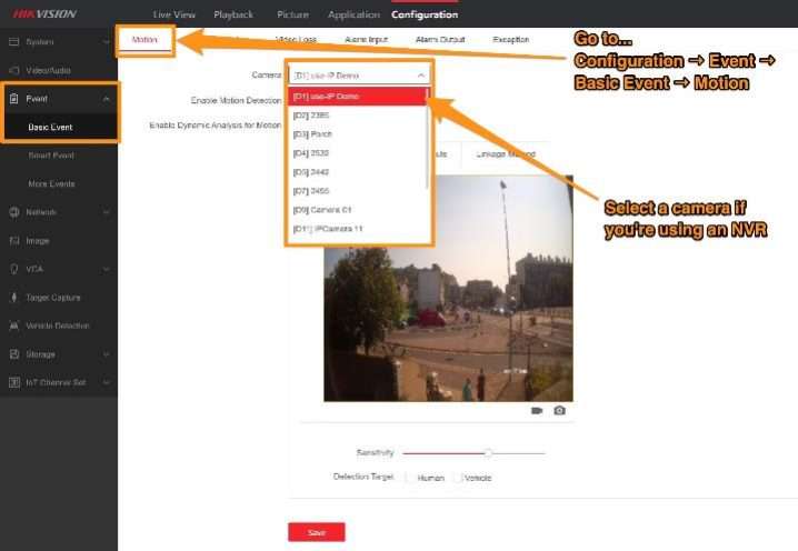
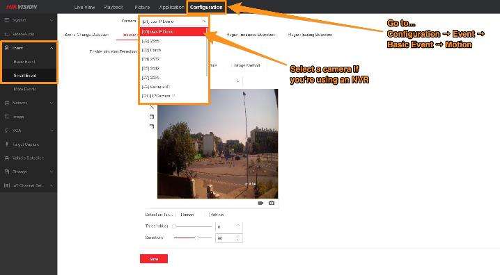
Configuration → Event → Basic Event → Motion
If you’re using an NVR, select your camera from the “Camera” dropdown.
Note – To set one of the other VCA event options, you’ll need to go to “Smart Event” rather than “Basic Event“, where you will be shown a list of tabs with all the other available events on your camera.
Step 3:
Tick the “Enable Motion Detection” box.
Step 4:
Decide if you want to enable “Dynamic Analysis for Motion”. When this is turned on, green squares will show on anything that triggers motion detection in the camera’s feed, which can help with identifying exactly what has triggered the event.
Note – Cameras usually determine what is ‘motion‘ in your scene by detecting pixel changes in the image, as a large amount of pixel change usually indicates movement. However, if there is lots of visible noise in your image due to gain control in low light, you will probably see a high number of false alerts on the camera. Using one of the more advanced event types, or the camera’s built-in LEDs to illuminate the scene, will help here.
Step 5:
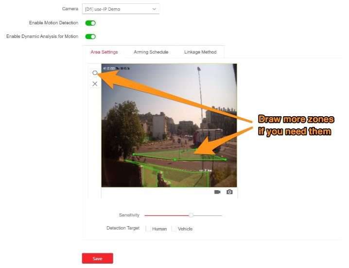
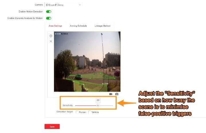
Once you’re happy with the view of your scene, click on the hexagon or “Draw Area” button in “Area Settings”, which will allow you to use your mouse to draw the area within which you would like motion detection to be active.
On Easy IP 3.0 and earlier cameras, These areas will be indicated by a red grid or polygon that appears when you click on part of the scene.
The newer cameras will get you to draw one solid shape for each of your detection areas by left-clicking to set each point of that shape. When you have set all the points that you need, right-clicking will complete the shape and allow you to draw any others that you need.
To clear your zones, just click the cross or “Clear All” button.
Note – If you are not using an AcuSense camera or NVR, then you should make sure that the edges of your detection zones are not on top of anywhere that is likely to see a lot of movement, shadows, or reflections (e.g. roads, foliage, windows or the sky), to mitigate the number of false triggers.
Step 6:
If you’re using an EasyIP 4.0 camera, draw any more detection zones that you need by repeating step 5 above.
Step 7:
Adjust the “Sensitivity” bar if you need, which determines how sensitive the detection is to pixel changes. The higher the sensitivity, the more easily motion detection is triggered, meaning you will receive more alerts as a result.
A good starting point for the sensitivity is 60, but you will likely need to tweak this yourself over time to identify the optimum setting for your scene.
If there is lots of activity in your scene, then avoid setting the sensitivity too high so that you don’t receive lots of false-positive triggers.
Note – In the case of Line Crossing and Intrusion Detection, the sensitivity setting refers to the amount of an object that is needed to cross the line, or enter the box that you’ve drawn, before the event is triggered.
Step 8:
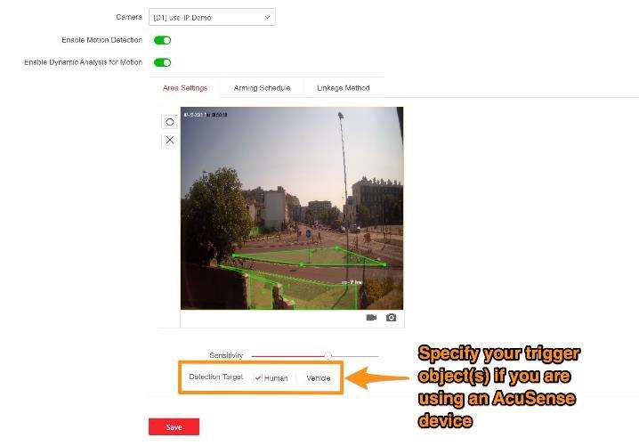
If you’re using AcuSense features, then use the “Detection Target” boxes to specify what you want to trigger the event. You can select both “Human” and “Vehicle” here if you are interested in both.
Step 9:
Click “Save” at this point so that you don’t lose these settings.
You’ll now need to go to the “Arming Schedule” and “Linkage Method” pages to set when you would like the event to be active, and what you would like to happen on triggers.
Please refer to sections 4 and 5 below for instructions on how to set these things.
Section 2: Setting up line crossing detection
Step 1:
In a web browser, go to:
Configuration → Event → Smart Event → Line Crossing Detection
If you’re using an NVR, select your camera from the dropdown at the top of the page.
Step 2:
Tick the “Enable Line Crossing Detection” box.
Step 3:
Click on the line button or “Draw Area” to draw your line on the video feed – you can move, rotate or resize however you like.
Step 4:
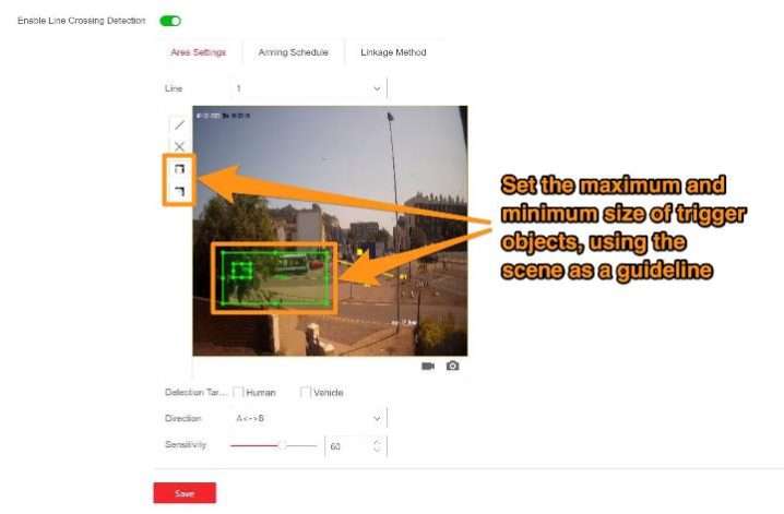
Set your maximum and minimum target sizes by clicking the size filter buttons, and drawing these on the camera preview.
Anything that crosses your line and is smaller than your minimum box, or larger than the maximum box, at the point of the line, will not trigger the event.
You should use objects or vehicles in the scene to guide you here. For example, I have set the minimum target size to be slightly smaller than any car that’s near where I’ll draw my line, and the maximum to be slightly larger than a large HGV.
Note – It doesn’t matter where boxes are on the feed. Also, these boxes will only be visible on this event page, and will not show up on your footage in the live view or playback pages.
Step 5:
If you’re using an AcuSense camera or NVR, then specify the “target(s)” that you would like to trigger the event by ticking the box. There is no issue with ticking both “Human” and “Vehicle” here.
Step 6:
Specify your “Direction”, which refers to the direction from which an object much cross your line to trigger the event. The different options available are explained beneath:
A<->B – Any object crossing from either direction will trigger
A->B – Any object crossing from side “A” to side “B” will trigger (In this case, from left to right)
A<-B – Any object crossing from “B” to “A” will trigger (In this case, from right to left)
Step 7:
Adjust the sensitivity bar to suit your needs. Setting this high will reduce the amount of an object that is needed to cross your line before this is triggered. This will, of course, result in more triggers. As the optimum setting here depends on how busy your scene is, we recommend starting at 60 and then adjusting the bar over time until you find the best results.
Step 8:
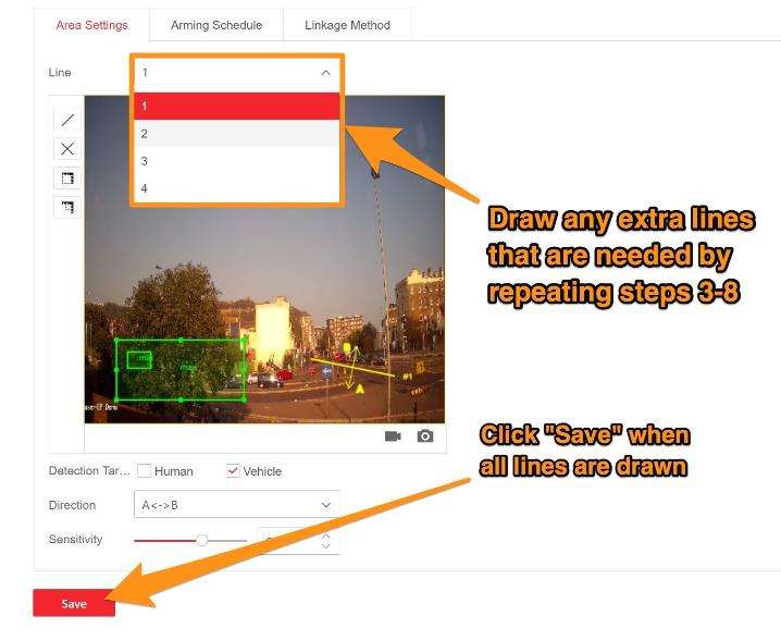
Use the “Line” dropdown to select and draw any more lines, repeating steps 2-8 above.
Step 9:
Click “Save” at this point so that you don’t lose these settings.
You’ll now need to go to the “Arming Schedule” and “Linkage Method” pages to set when you would like the event to be active, and what you would like to happen on triggers.
Please refer to sections 4 and 5 below for instructions on how to set these things.
Section 3: Setting up intrusion detection
Step 1:
In a web browser, go to:
Configuration → Event → Smart Event → Intrusion Detection
If connected to an NVR, select your camera from the dropdown at the top of the page.
Step 2:
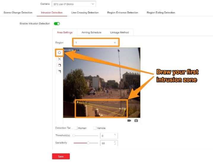
Tick the “Enable Intrusion Detection” box.
Step 3:
Click on “Draw Area” to draw your intrusion zone (or “Detection Area”) on the video feed, which can be a 3 or 4 sided shape. Left-click on the camera preview to set each of these points. Once your zone is drawn, you can still move each of the points to change the shape to better fit your area of interest.
Note – If the edges of your zone are very close to a road, foliage, or anywhere that is likely to see lots of movement, then you will likely see a number of false-positive alerts. This is because any movement on these lines can trigger the event. If you can, you should allow for a bit of a gap between these parts of the scene and your intrusion zone.
Step 4:
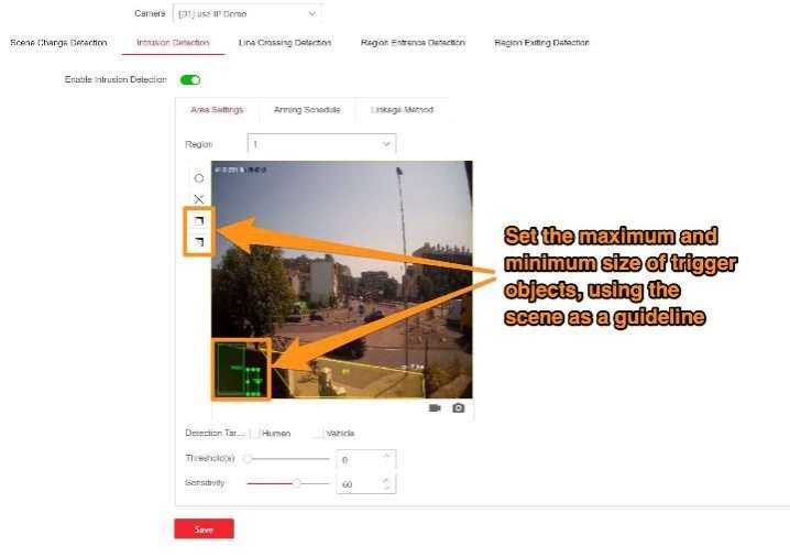
Set your maximum and minimum target sizes by clicking the “Size Filter” buttons, and drawing these on the live camera feed above.
Anything that enters your configured intrusion detection zone and is smaller than your “Min” box, or larger than the “Max” box, will not trigger the event.
You should use objects or vehicles in the scene to guide you here. For example, I have set the minimum target size to be smaller than the smallest person I’d expect to see in that part of the scene, and the maximum to comfortably cover a very tall person.
Note – It doesn’t matter where boxes are on the feed. Also, these boxes will only be visible on this event page, and will not show up on your footage in the live view or playback pages.
Step 5:
If you’re using an AcuSense camera or NVR, then specify the “target(s)” that you would like to trigger the event by ticking the relevant box. There is no issue with ticking both “Human” and “Vehicle” here.
Step 6:
Now, adjust the “Threshold” bar as you need. This can be set between 1 and 10 seconds and refers to how long an object needs to be within your intrusion zone before triggering the event. For example, setting this to “0” will mean that the event is triggered as soon as a valid target enters your zone.
Step 7:
Adjust the sensitivity bar to suit your needs. Setting this high will reduce the amount of an object that is needed to enter your zone before the event is triggered. This will, of course, result in more triggers. As the optimum setting here depends on how busy your scene is, we recommend setting this to 60 and then adjusting the bar over time until you find the best results.
Step 8:
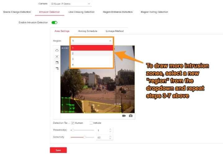
Use the “Region” dropdown to select and draw any more intrusion zones, repeating steps 2-6 above.
Step 9:
Click on the “Arming Schedule” tab and set this by filling in the hours you want the event to be enabled for in blue.
Note – Please see section [1] step 9 above for a more detailed explanation on how to set your arming schedule.
Step 10:
Click “Save” at this point so that you don’t lose these settings.
You’ll now need to go to the “Arming Schedule” and “Linkage Method” pages to set when you would like the event to be active, and what you would like to happen on triggers.
Please refer to sections 4 and 5 below for instructions on how to set these things.
Section 4: Setting the Arming Schedule for your events
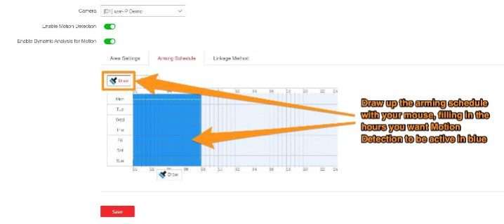
Now that you have set your “Area Settings”, click on the “Arming Schedule” tab to set when the event will be active.
This will bring up a timeline with the week broken up into days and hours – depending on the device that you are using, it might look different to the grid below. If a period is filled in blue then the event will be active (or “armed”) for that hour; If the period is white, the event will be off.
Use your mouse to draw up the weekly Arming Schedule that suits. You can also use the popup box that appears when you click on any blue period to finely adjust the start arming times:
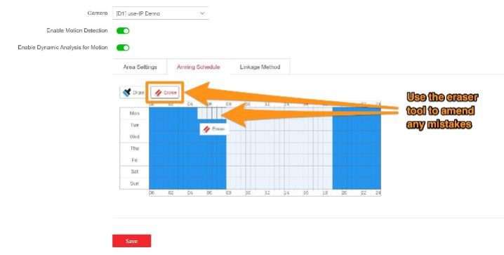
Clicking on the “Erase” button and then a blue period will allow you to clear the arming:
When you’re happy with this schedule, click “Save”.
Section 5: Setting up email & push notifications for your events
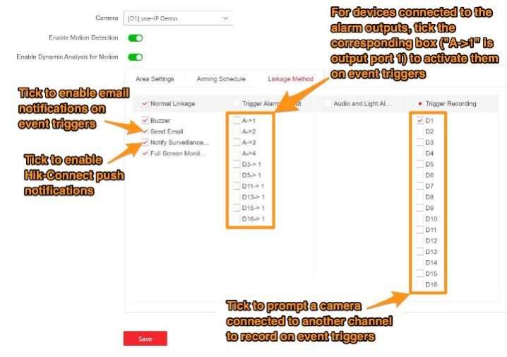
Click on the Linkage Method tab on the event’s page (shown above), which is where you will set up your email notifications, as well as other alert types.
The different options are explained below:
Audible Warning: This will cause the NVR / browser to bleep when on event triggers.
Send Email: This will set the NVR to email you on event triggers, with a screenshot of the camera’s view at the time.
Notify Surveillance Centre: This refers to Hik-Connect and needs to be activated in order to receive push notifications in Hik-Connect.
Full Screen Monitoring: This will get the NVR to automatically throw up a camera’s live feed in full screen during a trigger for an event set on that camera.
To enable Hik-Connect push notifications:
To set up push notifications, you need to make sure that Notify Surveillance Centre is ticked as a “Linkage Method”.
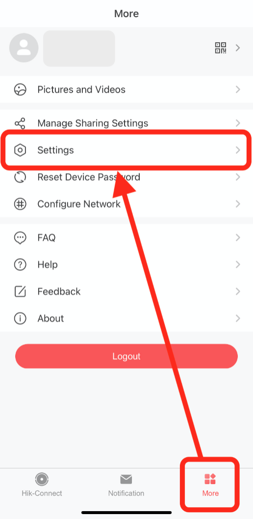
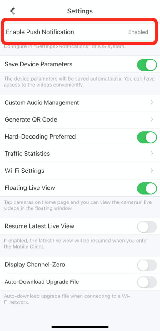
You also need to make sure that push notifications are enabled for Hik-Connect in your phone’s settings. To enable them via the app, go to:
More → Settings → Enable Push Notification
……..
NB – Please see here for instructions on getting a device added to your Hik-Connect account and using the app, which you will need to have done for push notifications to work.
To enable email notifications:
NB – As of June 2022, Gmail email accounts no longer work for sending email notifications, as they no longer allow third-party apps or devices to use your account. Please see this article for a full explanation:
As of the 30th May 2022, Google has removed the support for use of third-party apps or devices which can use your Gmail address using only your username and password. Google’s statement about it is here: https://support.google.com/accounts/answer/6010255?hl=en As CCTV cameras and recorders…
If you’re using the Send Email function on event triggers, you’ll need to set up an email account on your NVR to send and receive these alerts. To do this, go to:
Configuration → Network → Advanced Configuration→ Email
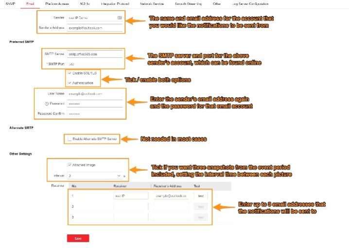
Now, fill out the fields, using the below as a guide:
Sender: This can be whatever you like, it is just what the sender will be named in the emails that you receive.
Sender’s Address: The email address that will be used by the device to send Emails.
SMTP Server: The SMTP server of the Sender’s Address. This varies with each email provider, you can normally get this information online from your email provider. TurboSMTP’s “What is my SMTP” page can also prove to be useful, as it lists several of the main providers’ SMTP servers.
SMTP Port: Like the above, this varies with each provider and this information should be published by them online. This port number can also vary with the encryption type. E.g., Google’s port for SSL encryption is 465, and 587 for TLS encryption. Port 25 should be fine in most cases. However, if this port is blocked, 465 or 587 should work too.
Email Encryption: SSL is an older version of encryption and should be supported by most providers. TLS is newer and often preferred, but check that your provider supports this – NVRs with the newest firmware will detect this automatically.
Enable STARTTLS or Enable SSL/TLS: Enable this.
Authentication: Tick this box.
User Name: The email address that the NVR is using to send email alerts.
Password: The password for the email address that the NVR is using to send email alerts.
Password Confirm: Insert this password again for confirmation.
Attached Image: If you want to be emailed an image of the camera view during the event period, tick this box.
Interval: This is just the length of time before the event is triggered and the attached image is sent. “2s” (2 seconds) normally works well.
Receiver: Insert the names and email addresses of anyone you would like to be sent email alerts from this device.
Use the Test button to confirm that the receiver’s details are correct and working, and then click Save.
That’s everything that you need to do to receive email alerts, we always suggest forcing an alert trigger yourself to confirm that everything is working as you’d expect. Your device should also attempt to send a test email after saving these email settings.
